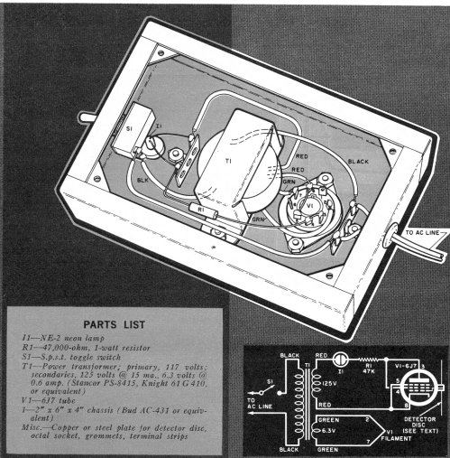
I found the circuit below by accident, while flipping through my library of Popular Electronics looking for something else. It was published in the October 1961 issue, and caught my interest because a friend of mine built it back in 1964. It was a cool thing to watch in action. It’s an electroscope that detects static charge by using the grid in a vacuum tube to control conduction. Bring an object with a static charge on it within a couple of feet of the detector disk, and the NE-2 neon bulb will light or dim, its brightness proportional to the strength and polarity of the charge. Positive charges make the bulb glow more brightly. Negative charges will dim it, or even darken it completely if the charge is strong enough to force the tube into cutoff.

(The full article can be found here–2.6 MB PDF.) The detector is a metal disk five or six inches in diameter. It can be any conductive metal. When Art built his he used sheet aluminum and it worked just fine. The center hole is sized to press-fit on the grid cap of a 6J7, which is connected to the tube’s control grid. The 6J7 works well here because it’s a metal tube, and is inherently shielded by its metal shell. (The article doesn’t call it out, but I think pin 1, connected to the shell, should be grounded to the chassis.) A 6K7 or 6S7 will substitute pin-for-pin, and I think any metal tube with the control grid brought out to a cap will work if you get the pin connections right for the tube type. NOS tubes of this sort can be had for $5-$6 from places like Antique Electronic Supply. I don’t know how well the GT (glass) versions of the tube will work, since they lack the total shielding of the “standard” 6J7’s metal shell.
The power transformer called out was common and cheap back in the day, but you’d be hard-pressed to find one now. The usual dodge is to use two 6.3V filament transformers, and connect them back-to-back. (These used to be sold at Radio Shack. I’m not sure if they are anymore.) You can light the filament from the joined 6.3V secondaries, and take isolated 120VAC from the primary of the second transformer. The 6J7’s heater current is 300 ma. Any filament transformer that can source that much current will do.
I find it interesting that raw AC is applied to the plate of the tube without rectification. The current is in fact rectified by the tube (tubes conduct in only one direction) with rectifier current controlled by the 6J7’s first grid. My first thought was that it works like a thyratron, but there’s no latching effect. Current through the tube is controlled by the charge on the grid, and then in a linear way.
It would be interesting to figure out a circuit that would indicate with a sensitive meter rather than a neon bulb, and if I build it I may try a few things. The only cautions I offer here relate to the voltage: 120V, even isolated from the wall, is dangerous. Don’t work on the circuit with power applied. To be safe, yank the plug out of the wall before you open the box or flip the chassis over. There’s no voltage on the detector plate, so that can be touched even while the device is on.
All that said, it’s a great entry-level demonstration of how vacuum tubes work.


Interesting circuit. I would expect some care will be required to minimize leakage around the tube socket and it might be necessary to select a vacuum tube with low gas, as NOS tubes have been sitting on someone’s shelf for 40+ years now.
Screen grid connected to plate, suppressor grid connected to cathode. That’s a normal pentode arrangement.
The control grid will have some space charge from the electrons boiled off the cathode that are intercepted by the grid wires, and I would have thought, without a detailed analysis, that the space charge on an open circuited control grid would drive the tube into a low current range, possibly near, if not at, cutoff.
It may well be that some degree of leakage (grid leak bias) is important to make the circuit work. Boonton’s 260A Q-meter used a 100 Mohm grid leak resistor in the detector circuit and a triode factory selected for minimum leakage. (Boonton part number 535A, but it’s apparently a selected 2A6 from what I’ve read.)
But, it’s been so long since I’ve done serious vacuum tube work that my impressions are wrong.
I don’t know how good the insulation is around the grip cap of a 6J7 (I haven’t opened up a metal tube since I cracked an 0Z4 in 1966 to see whatthehell was inside a filamentless tube) but I can’t imagine it’s as good as clean glass or ceramic if the tube’s been used and is typically grubby. If there isn’t sufficient leakage to bleed space charge from the grid, I’ll play around with getting the insulation around the cap artificially dirty. It may not be a problem at all. We’ll find out.
Yes, an interesting application for an old technology. I agree that the grid leak effect may well leave the tube biased to cutoff. I have a couple of these old tubes (a 6J7 and 6K7) and may have to try it.
An easy way to get the transformer is to use one with dual 120v primaries. Use one for the primary, and one for the high voltage secondary. The normal secondary can power the tube filament (with a dropping resistor if the voltage is too high).
I have an old VTVM that uses a more sophisticated variation of this circuit. It has a twin triode in a classic differential amplifier configuration, running on a 300vdc supply. The amplifier is balanced when both grids are at the same voltage. One grid is the unknown voltage. The second is driven to whatever voltage it takes to achieve balance. The meter reads this second grid voltage. This method provides a nearly infinite input impedance (in fact, it has a 22meg 20% resistor in the probe, which doesn’t affect accuracy at all). But it only reads to +/-100v, since it doesn’t have the usual range resistors on the input.
Another interesting use for this sort of circuit. On AC, this VTVM is flat to over 100 MHz. The tube acts as a very good high frequency rectifier. On AC, there is a 2pf capacitor in series with the input, which is so small that it has a negligible effect on most circuits, but not enough impedance to affect accuracy even at 60hz.
Of course, you might be able to do all this with FETs. But it would be hard to protect them against static discharges without compromising the very high input impedance.
Joe Flamini wrote to tell me that All Electronics has 12.6VCT filament transformers for $7.60. See:
http://www.allelectronics.com/make-a-store/item/TX-121/12.6-V.C.T.-1-AMP-POWER-TRANSFORMER/1.html
Part of the circuit’s charm is its simplicity–rather like a superregenerative receiver. Static charge is easy in our dry air, even in summer, so as winter approaches this becomes a compelling one-evening project.
There’s another interesting feature to the design – the series NE2 lamp. During the portion of the AC plate voltage cycle where the voltage is less than the NE2’s firing voltage (around 60 volts as I recall), the NE2 will be an open circuit.
The plate voltage seen by the pentode, therefore, is baseline clipped by the NE2’s firing voltage. When fired, of course, the drop across the NE2 is much less, a matter of a few volts. I don’t see this as an essential part of the design.
The circuit Lee describes sounds interesting – is it a Ballentine instrument? My Agilent 34410A 6.5 digit multimeter has a selectable DC voltage input impedance of 10 Mohms or > 10 Gohms. It’s actually a lot greater than 10G ohms, I think, as you can read a DC voltage, disconnect the probe and watch the voltage stay constant for minutes or more as the input capacitance very slowly discharges.
There’s a Bob Pease column around somewhere concerning how good an FET is for leakage – I think he charged up the input capacitance (a few pF) with a DC source and found it would retain the charge for days.
Can’t find that Pease column, but one almost as good is at http://www.national.com/rap/Story/0,1562,4,00.html regarding Teflon and how low leakage it is.
OK it has been a couple years, but the link to the original article does not seem to work, although the info at the top is sufficient to build it I would think. Some genius could build these and use vintage parts and appearance, and sell them on ebay as ghost detectors, a much more exciting potential use than watching your comb light it up, and make alot of money!
I don’t know where the full article went, but I can repost it when I’m back with my archives. The meat of the piece is on that single page. The rest is the conventional how-to-build-it text plus a photo of the finished gadget. Anybody who can read a schematic should be able to duplicate it. Better electrometers can be made with FETs, though they don’t have as much steampunk whiff as something using tubes would have. Never thought about ghost detectors. You’re right about that, heh. Me, I’d use it to detect thunderstorms.
Hey, that’s the article which warped my mind as a kid! It was in a 1960s paperback of P.E. ham radio articles. 1971! That was the second device I’d ever built, the first being that houseplant-emotions GSR project with a ua741 op amp.
I knew enough back then to ignore the isolation, and just used a 6.3V transformer and a polarized power plug so the cathode went to AC neutral. For the “Antenna” I epoxied the metal lid of a can of coffee to a grid cap, soldered the wire to the steel (difficult!), then protected the sharp can-opener-d edge with the poly coffee can lid. Not much allowance, so I skipped lunch for weeks so that I could buy the 6J7 tube mail order. Then it all was destroyed in the great NY flood of ’72.
See the link for current FET-based version, warping the minds of unsuspecting youth in the 2000 era.
[…] lashed it up on a scrap of perfboard with a total of three solder joints. Bill found me because of this post, to an old Popular Electronics electroscope project using a 6J7 tube instead of an FET. (They […]
Jeff,
The link for the full article, here given as:
http://www.copperwood.com/pub/TEST%20GEAR%20-%20PE%20-%201961%20-%2010%20-%206J7%20Electroscope.pdf
Does not work. 404 error.
This reminds me of the mention of an EF37A circuit in the book -Electrical Measurements-by Golding which the author says ,has 50 M Ohm input impedence. I had no idea that the 6J7 can as well do the job.Considering the fact that later tubes such as 5879,EF86 ,etc were specially built for low leakage and hum,I wonder what input impedence they are capable of,paricularly when used with slightly deceased heater voltage.
Thanks! If you try that, post again here and let us all know how it works. I’m working hard on a book project now, but when that’s done (mid-January) I intend to sit down and build me some projects, including this one.
This was my fifth grade science fair project!
A friend of mine built one when we were 12 or 13. It was very cool. I never got around to building my own, but now, in retirement, I don’t have a lot of excuses. Thanks for reading!