The air conditioning condensate drain clogged earlier this week, and it may have been dripping water inside the air handler for several days. I only noticed it once it started spilling out onto the utility room floor. So we shut the damned thing off until Monday, which is as soon as the HVAC guys can get out here to poke at it.
Oh, and it’s been hot. 2003 was hotter here, but 2011 is right up there. My internal thermionic detector was detecting some thermic excess, so midafternoon yesterday I went downstairs to my shop, where it’s 5 degrees cooler. After spinning the dials to make sure nobody was having any fun on 10 meters that I wasn’t having, I sat at the bench and looked around. Something, somewhere had to need fixing.
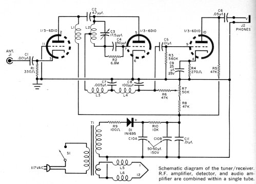
Oh. Yes, of course. Back in 2008 I built a 1-tube FM BCB receiver pretty much on a lark, from the Popular Electronics article in which GE introduced the Compactron tube. The article, “Introducing the Compactron,” by Phil Hatfield W9GFS, talked about some of the challenges of stuffing as many active elements into a 12-pin bottle as could be done. This was the last gasp of the vacuum tube, but GE gave it a good shot, and in August 1961 having as many as four active devices in one envelope was still pretty hot.

50 years ago…just about now. The example circuit was an FM BCB receiver using a single 6D10 triple triode tube. I had all the parts (even the tube) lying around, so on a whim I built it.
It worked, but it had several defects. One was touchy tuning due to hand capacitance. This is always a problem when both sides of the tuning cap are above RF ground. Another problem was that the tuning range was too wide (about 65 MHz – 120 MHz) and the entire FM band was crammed into about 20 degrees of rotation of the shaft. The last problem was that the regeneration control was just, well, nuts.
The first problem was beyond help; 50 years ago we just lived with hand capacitance. I tried to fix the second problem in 2008 but didn’t improve matters much. I’d painted myself into a corner with the physical arrangement of the tuning coil, and couldn’t easily swap it out. The third problem was still undiagnosed when I set the radio aside to do other things.
So I pulled it down off the shelf, patched it into my bench supply, and powered it up. Still worked; regeneration still nuts. I spun it, listened, spun it some more, and listened some more. (Why do I hear that song with “She wears short-shorts; I wear T-shirts…” every damned time I turn on the radio?) Regeneration was erratic, happening at different points on the pot, and sometimes didn’t happen at all. Alas, I was overanalyzing the operation of the superregenerative detector, thinking maybe I was driving the detector too far in one direction or another. Occam hit me in the head with a frying pan about then: The regeneration pot was bad.
Duhh. The wiper was making only marginal contact with the resistive element. Not sure why. Don’t care that much. Fished a new 50K pot out of the drawer, soldered it in, and wham! Regeneration worked as it should.
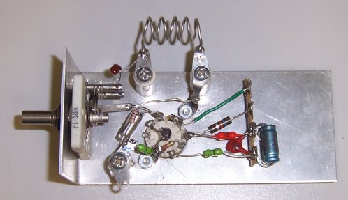
Having fixed one out of the three problems, I was on a roll, and being on a roll…I started to build another radio. John Baumann KB7NRN has a design for a similar detector with a grounded rotor. I’ve been intending to build it since, well, 2008, and had most of the parts set aside in a milk jug. So with the upstairs mostly uninhabitable until Monday, I got to work downstairs last night, and have gotten pretty far along on the RF portion of the circuit.

This is only a lashup; once I get the circuit working as I want, I’m going to build another instance on a conventional chassis with its own power supply. It’s going to take a few more evenings to get to the smoke-test stage, but I’ll let you know the rest of it comes along.


Hewlett Packard made a super-regen VHF receiver in the 1950’s, model HP-417A. I have one that makes up my suite of ca. 1960 VHF impedance measuring tools, HP 608 signal generator, HP 803 bridge and HP-417A VHF detector. Details and some photos at http://www.cliftonlaboratories.com/hp_803a_vhf_bridge.htm
If you care to see how HP built a super-regen receiver, the operating manual and schematic can be found at http://www.hparchive.com/Manuals/HP-417A-Manual.pdf
The tuning capacitor is a split stator type, floating, but the input stage is in a separate shielded enclosure, in the usual HP quality style.
It’s quite a decent receiver, sensitivity is in the 2 or 3 uV range. Selectivity is terrible by modern standards, but it was never intended to be used with an antenna, but rather as a null detector with a bridge and signal generator.
Jack
“hand capacitance” – is that why all those old radios had tuning dials connected to the tuning capacitor with pulleys and long loops of black thread?
No, that was (typically) for pulling a pointer along a linear dial, though sometimes to “slow down” the turning of the cap but putting what amounts to reduction gearing on it. Hand capacitance “pulls” the resonant frequency of the tuning circuit slightly, making tuning more art than science. You grab the knob and turn it to your station of choice, and then let go–and resonance jumps 300-500 Hz. Not a huge problem on AM or broadband FM, but often a hideous problem on CW or SSB.
I love these old circuits, Jeff. Thanks again for putting them up. Every time I see one, I want to jump right in a build it!
I still have many fond memories of building these sorts of projects. Ah, those were the days! The parts were big enough for my beginner’s fumbling fingers. The component counts were low enough that I could afford the parts on my meager allowance (or scrounge them out of junked TVs and radios). They were simple enough to build the whole thing in a weekend, and (usually) get it to work. I learned a *lot*, which came in handy later in life to earn a living. And, they did something neat to impress my friends. What more could you ask for!
I did that too, but I had a lot more trouble getting things to work. (This is one reason I’m doing such projects today: To vindicate my 12-year-old self from self-indictment on gross incompetence charges .) I had almost no test equipment beyond a cheap Lafayette VOM, and I think a lot of the parts I used were marginal or just dead. (Unmarked “Floor-sweepings” transistors in a bag from Olson Electronics or EDI were cheap–and probably faulty.) I remember discovering that a number of supposed mica capacitors I had snipped out of one curb-corpse or another weren’t capacitors at all–they were wirewound resistors! Whence comes my ironclad rule: Test every component twice before you solder it into a layout. Things have worked a lot better since I had that insight. Oh–and a scope, signal generator, tracer, dip meter, and transistor tester have helped as well!
I “had it made” when I was a teen (though I didn’t realize it at the time). Half a block away lived a ham who was a friend of my dad (Jim Firestone, K8SUC). I bugged him incessantly, and he helped me fix many of my artless conglomerations.
A half block in the other direction was Floyd Blighton’s TV repair shop. He went to our church, and took pity on me I guess. I was too young to hire, so he and gave me parts in return for sweeping floors and testing tubes. He also let me use his equipment and tools, and taught me a lot about fixing things.
On tools and test equipment: You *have* to read “The Boy Who Harnessed the Wind” by William Kamkwamba (if you haven’t already). He grew up in Africa, and learned electronics by fixing old radios, using parts from one to fix another, soldering with a nail poked in a fire, and with only light bulbs as his test equipment!
On dead parts: Remember Poly Paks “no chance to test” assortments? Used fuses? Unmarked “precision” resistors? 🙂
Just stumbled on to this, Jeff. My father-in-law, Philip Hatfield, was the author of that article 50 years ago. A quiet, brilliant man who went from tubes to microwave products (more likely guidance and landing systems than ovens!) during his tenure at GE. Glad you finally got the thing working after all these years!
–tj
I wish present day hams spend time with this kind of DIY projects, preferably vacuum tube regenerative and super-regenerative receivers, and build an 807 Transmitter with Pi output to the antenna and light up a handheld fluorescent tube!They will find the exercise worth it.They also need guidance to work with H.T, of course! Seniors are with them to help anytime. Keep the Iron hot! 73 de VU3NPY